Results
Publications: 1. M. Ruba, R. Nemeş, S. Ciornei, C. Marţiş and H. Hedeşiu, "A review on analytical methods for multilevel simulation of urban light electric vehicles," 2021 IEEE 19th International Power Electronics and Motion Control Conference (PEMC), 2021, pp. 377-382, doi: 10.1109/PEMC48073.2021.9432513. 2. Maria Raluca Raia, Mircea Ruba, Razvan Alexandru Inte, Claudia Martis, Gabriel Mihai Sirbuz, Calin Husar, "Modelling and Virtual Testing of a Wound Rotor
Synchronous Machine for Electrical Vehicles 3. Raul Nemesș, Mircea Ruba, Claudia Marțtis, " HiL testing of Li-Ion battery pack based on real-time virtual vehicle model ", IEEE Vehicular Power and Propulsion 2021 (IEEE VPPC 2021) , - in print 4. M. R. Raia, M. Ruba, R. O. Nemes and C. Martis, "Artificial Neural Network and Data Dimensionality Reduction Based on Machine Learning Methods for PMSM Model Order Reduction," in IEEE Access, vol. 9, pp. 102345-102354, 2021, doi: 10.1109/ACCESS.2021.3095668. 5. Raul Octavian Nemeș, Mircea Ruba, Sorina Maria Ciornei and Raluca Maria Raia, "Powerful Multilevel Simulation Tool for HiL Analysis of Urban Electric vehicle's Propulsion Systems", chapter of "New Perspectives on Electric Vehicles", ISBN: 978-1-83969-615-2, Intech Open Access 6. M. Ruba, R. O. Nemeş, R. Raia, C. Marţiş, D. Zuber and C. Husar, "Hardware in the loop analysis of urban utility electric vehicle powered from supercapacitors," 2022 International Symposium on Power Electronics, Electrical Drives, Automation and Motion (SPEEDAM), 2022, pp. 838-843, doi: 10.1109/SPEEDAM53979.2022.9842032. 7. A.Pop, M. Ruba, R. O. Nemeş, R. Raia, C. Marţiş, and C. Husar, "Benchmarking methods for parameters identification of supercapacitors using Typhoon HiL," 2022 IEEE 20th International Power Electronics and Motion Control Conference, 2022, - in print 8. A.Pop, M. Ruba, R. O. Nemeş, R. Raia, C. Marţiş, and C. Husar, "Digital-Twin based high accuracy test facility for industrial development of electric vehicles," IEEE Transactions on Transportation Electrification , 2022, - in print |
Technical report for the period: 2020 - 2022 WP1. Development of multilevel EMR components of the platform - Part I |
|
|---|---|
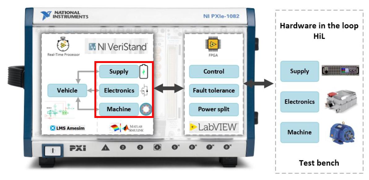
According to the project proposal, in the implementation plan the first work package of 2020 starts with an analysis of the literature for extracting multi-level simulation solutions of the 3 fundamental components of the system: battery, power electronics and motor propulsion (according to the red square in the figure below).
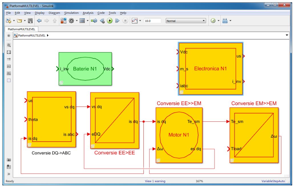
The MULTILEVEL platform will have a library in which the built components will be cataloged marking the level of complexity N1, N2 and N3 respectively. So far, the N1 levels for the 3 assemblies (battery, power electronics and motor) have been created, as can be seen in the figure below, all using EMR (energetic macroscopic representation) organization. Following a rich analysis of the international publications, three levels (simulation solutions) were outlined for each entity: battery (N1-ideal model, N2-circuit order I, N3-circuit order II), power electronics ( N1-ideal model, N2-with switching losses, N3-with switching losses and the influence of dead time) respectively for motor (N1-model in linear DQ representation, N2-model in DQ representation with variable inductances, N3-complete flux model).
The results of the project related to the period 15/09/2020 - 31/12/2020 according to the implementation methodology were fully met, reaching the objectives proposed for 2020. |
|
| Ongoing activities for the period: 01/01/2021 - 31/12/2021 | |
Phase 2 |
WP1. Development of multilevel EMR components of the platform - Part II WP2. Development of the electronic control unit (ECU) WP3. Fault tolerance and power distribution |
Act 2.1 |
Task 1.2. Development of multilevel models for battery simulation - Part II |
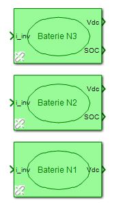
In the EMR libray of MULTILEVEL 3 battery models were added:
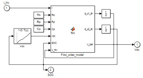
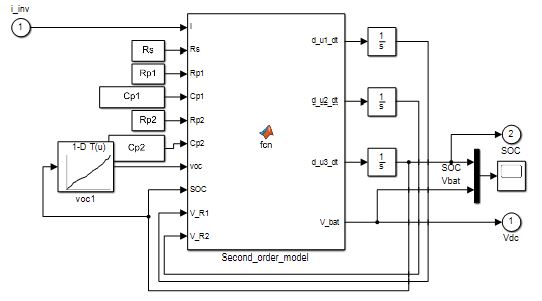
Initially, only the first level (N1) existed. Now levels N2 and N3 contain the battery models based on the first and on the second order electrical equivalent circuits. Their Matlab Simulink implementation is depicted below.
|
|
Act 2.2 |
Task 1.3. Multilevel models development for the power electronics - Part II |
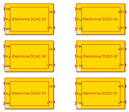
In the general library new models were added both for the DC/AC as for the DC/DC electronic converters. The inital model considered only ideal, non-switched voltage regulation. These new models, consider both PWM pulsing (for level N2) and PWM pulsing with transistor losses (level N3). The ERM pictograms added into the library are:
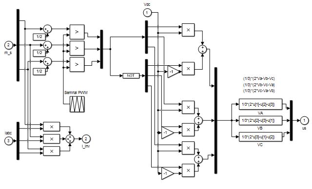
The content of the blocks is detailed only for one set of DC/AC and DC/DC converters in order to avoid redundancy. The 3-phase (DC/AC) converter is depicted below.
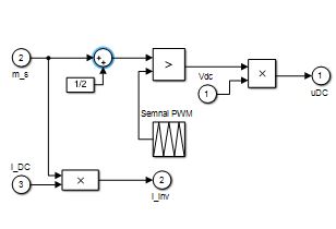
The DC/DC converter architecture in Matlab Simulink is:
|
|
Act 2.3 |
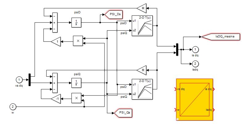
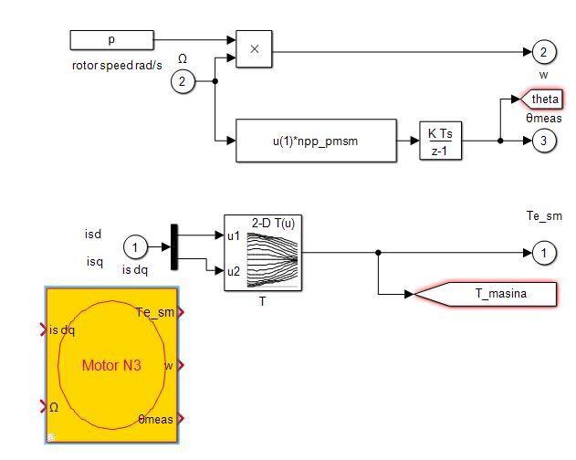
Task 1.4. Development of multilevel models for PMSM simulation - Part II |
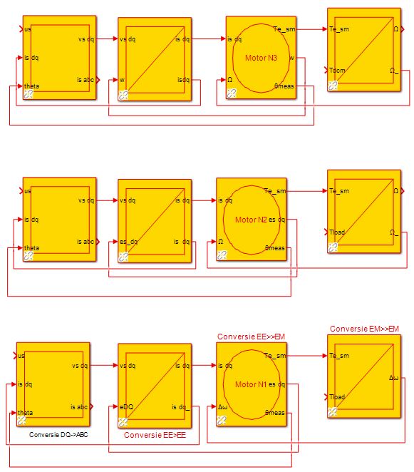
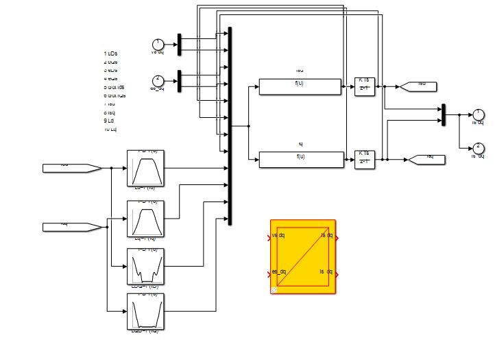
The MULTILEVEL library was completed with 2 new models of complexity for the simulation of the PMSM. The preliminary one was based on using constant DQ inductances. The new levels are designed to use variable inductances for level N2 and flux linkages for level N3.
For level N2 the simulation model is created using the following designs: -for the accumulation block (that models the windings)
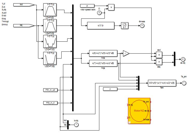
-for the electromechanical conversion
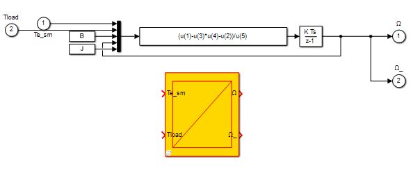
-and for the accumulation block that models the mechanical equation
For the most complex level, N3, the design in Simulink isdepicted:
|
|
Act 2.4 |
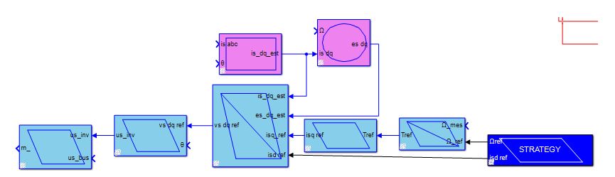
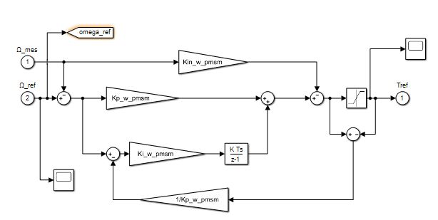
Task 2.1. Development of rotor field oriented control strategy |
In this section, the library was completed by the EMR scheme for the field oriented control strategy. This is practically the mathematical inversion of the model. Normally, accumulation blocks become PI regulators while the direct conversion blocks from the model, become inverse conversion block in the control unit, as delpicted below. The general FOC scheme in EMR is:
with the accumulation block inverted as PI regulator:
and the direct conversion block inverted as reversed mathematics:
|
|
Act 2.5 |
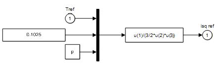
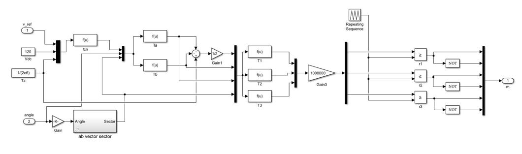
Task 2.2. Development of rotor field oriented control strategy with space vector modulation |
In this action, the team developped the space vector modulation control method that was then tested on a model.
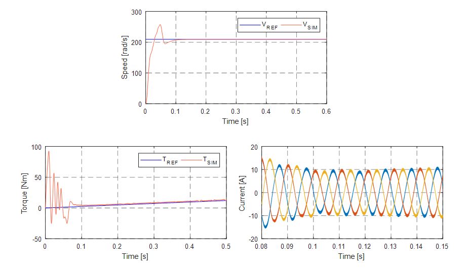
The simulation results prove the functionality of the model, this becoming part of the MULTILEVEL library.
It can be noticed that the control unit is able to manage the machine in order to follow closely the reference torque and speed. |
|
Act 2.6 |
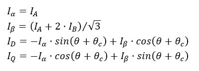
Task 3.1. Fault detection and compensation |
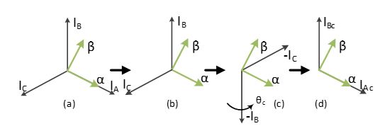
The method behind the fault detection and compensation method demands generating an estimated current (intsead of the faulted one), using the remaning two operational ones. In doing so, there is a need to rotate the referance frame of the Park transformation to keep computing correctly the DQ components. For this, the mathematical model bellow is usedȘȘ:
In doing so, we can obtain a new coordonate system that includes the two remaining currents to create the necesary DQ ones.
|
|
Act 2.7 |
Task 3.2. Power split function |
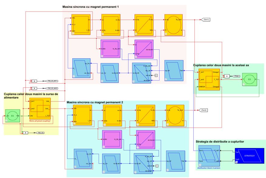
The power split function, preliminary needs to have a program tnat includes two motors. To do so, one such program was created in order to test the future algorithms.
The program designed is depicted in the picture above. The results bellow prove the functionality of the program, at the moment with manual control of the power split.
|
|
| Ongoing activities for the period: 01/01/2022 - 14/09/2022 | |
Phase 3 |
WP3. Fault tolerance and power distribution- Part II WP4. Experimental testing (Hardware in the Loop - HiL) |
Act 3.1 |
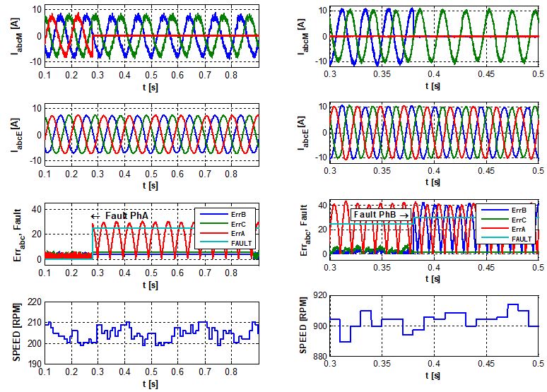
Task 3.1. Detection and compensation of sensors faults- Part II |
In the figure below it is visible that the system is able to perform both single and double fault compensations, making sure that the speed of the machine is not affected by the replacemenent of measured quantities with those estimated.
|
|
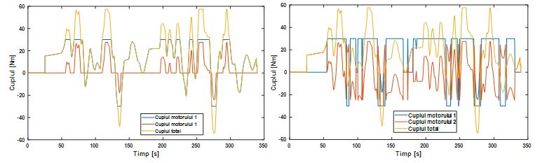
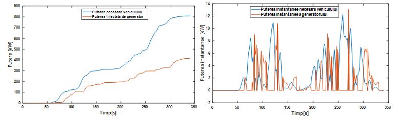
| Act 3.2 | Task 3.2. Power split distribution function- Part II |
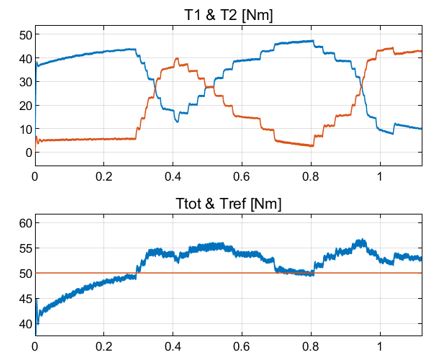
There were implemented two power split functions, one that saturated the torque to 30Nm and the second one was to nimimize the complete power consumption.
In the pictures above, the results of the 2 methods are provided. This proves that the models work and the power is divided between the motors. |
|
| Act 3.3 | Task 4.1. Installing the test bench |
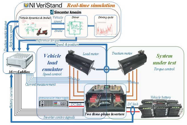
In the picture below the schematic of the testbench is provided. One can observe that the motor under test is fed from a battery while its load, from a bidirectional power supply. In Amesim software the vehicle mechanics are simulated.
|
|
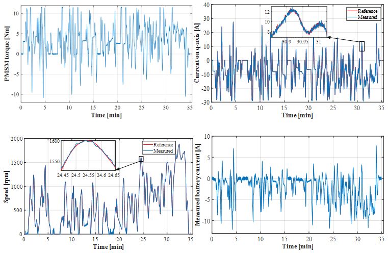
| Act 3.3 | Task 4.2. Experimental testing |
In the pictures below, the experimental results are presented. One can see the good agreement between references and measured results. These provide proof that both the complex EMR models and the testbench work as expected.
|
|